Electrical and mechanical design, verified against the standards

Design the data center.
Prove it before you build it.

A professional simulation platform for engineers, consultants and operators to design, test, renovate and validate data center power and cooling systems with confidence.
SLDvisual design
Real-timesimulation
Audit-readyreports
Compliance Test 2N
LIVE MODEL
Data Center Simulator designer interface
SYSTEM RESILIENCE
99.982%modeled availability
Utility failure injectedCritical loads transferred in 3.0 s
REPORT READY Tier III drill passed
Scroll to enter the digital twin
0infrastructure components
0simulation modes
0%modeled availability
0 clickfrom design to drill
ONE CONNECTED ENGINEERING ENVIRONMENT

From first concept to verified operation.

Build the electrical and cooling architecture, simulate failures, compare options and generate evidence — without leaving the same model.

01

Design visually

Build single-line diagrams and infrastructure relationships using a precise drag-and-connect workflow.

  • Power sources and transfer
  • UPS, batteries and PDU chains
  • Cooling and rack dependencies
02

Simulate in real time

Inject utility failures, EPO events and maintenance scenarios while the model calculates the impact live.

UTILITYOFFLINE
GENERATORONLINE
03

Validate compliance

Run repeatable drills and capture evidence for resilience, maintenance and operational readiness.

92/100Design readiness score
04

Renovate what already exists

Capture the facility as it stands, draw the works, and see the difference: what the plant you are reusing has left, and what Tier you reach at the end of each phase.

II → IIITier movement from the works
05

Turn every test into a decision-ready report

Automatically document topology, assumptions, calculations, events, alarms and recommendations for stakeholders.

See report intelligence
STANDARDS & COMPLIANCE

Not an opinion. A verdict against the codes.

Most tools draw a diagram. This one grades it. Every design is measured against Uptime Institute Tier topology and ANSI/BICSI 002 Class criteria, and every finding cites the clause it comes from.

UPTIME INSTITUTE
Tier ITier IITier IIITier IV

Topology is traced from utility to load. N, N+1, 2N and 2(N+1) are detected from the single line you drew — not from a checkbox you ticked.

ANSI/BICSI 002-2024
F0F1F2F3F4

Availability Class is assessed across the electrical, mechanical, telecommunications and fire subsystems, and the weakest one sets the class.

The Applicable Codes & Standards Register

76 normative documents, grouped by what they govern — grounding, batteries, fire, cabling — so every code that applies to one part of the design sits in one place instead of scattered across chapters. It prints into the report as a signed-off register.

76codes
14 subjects
12Telecommunications Cabling
10Fire Detection & Suppression
10Stored Energy (Batteries)
6Electrical Power
6Grounding & Bonding
6Architectural & Access Floor
5Mechanical & Plumbing
4Lightning & Surge
4Building & Structural
4Physical Security
3Generators & Fuel
3Commissioning & Maintenance
2Wireless & DAS
1Reliability & Availability
ANSI/BICSIUptime InstituteNFPAIEEE ANSI/TIAIECISO/IECASHRAE CENELEC ENULICC — IBC / IMC / IPCASCE ASTMNECACISCA

Edition policy: unless a specific edition is quoted, the current adopted edition applies, as adopted by the Authority Having Jurisdiction for the project locale.

The register is a full-licence feature. The demo gives you the real Tier and Class verdict on your own design — the code citations behind it come with the licence.
RENOVATION & BROWNFIELD

Most data center work is not a new building.

It is a hall being extended, a plant being reused, or a live facility being taken from one Tier to the next without ever going dark. The software holds the facility as it stands today beside the one you propose, and reports the difference — in capacity, in Tier, and in scope.

THE QUESTION THAT DECIDES THE SCHEME
TR-1 · 2500 kVA 2000 kW usable 80% Legacy building 1400 kW New hall 420 kW Spare 180 kW 91% loaded · TIGHT it fits — with nothing left for the next phase

The existing transformer is rated 2500 kVA and already carries 1400 kW of the legacy building — is there room for the new hall hanging off it? A site-level capacity check cannot answer that. This one walks the diagram downward from every item you are reusing and adds up only the load that actually reaches it, then flags each one ok, tight above 80%, or over.

TIER MOVEMENT, WITH THE EVIDENCE
Tier ITier IITier IIITier IV

“Tier II to Tier III” is the claim. The evidence is both designs graded check by check: which requirements the works fix, which they leave untouched, and — the one that matters on a live floor — whether they quietly break something that used to pass.

Draw the works. The scope writes itself.

Capture the facility as it stands, then just draw the renovation. Nothing has to be tagged by hand: a component in both documents was retained, one present only in the capture was removed, one present only now is new. Deleting a component is marking it for demolition.

5views on
the same works
Utility 11 kV TR-1 2500 kVA SWGR-A SWGR-B New hall UPS-1 old Retained New Removed — deleting it is what marks it for demolition
One drawing, three states. The disposition is worked out by comparing your design against the capture — nothing is tagged by hand.
TwinThe same fault run against the existing facility and the proposal — the difference is the case for the works
CodesCompliance before and after, lined up check by check
ScopeEvery component sorted into retained, removed and new
PlantSpare capacity and utilisation on everything you are reusing
PhasesThe Tier you reach at the end of each construction phase, not only on the last day
LIVE WORKFLOW

The model changes.
The system explains why.

Move through design and simulation without breaking context. Every component, dependency, alarm and calculation remains connected.
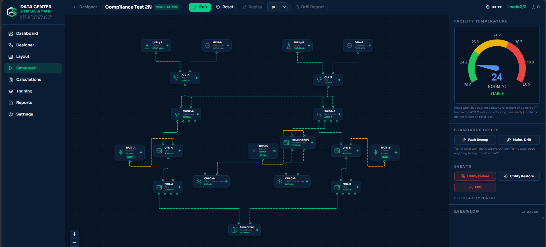
Designer workspace
Designer workspace screenshot Simulator workspace screenshot
INTERACTIVE DIGITAL TWIN

Watch power move through the design.

Select an operating scenario. The simplified network below updates live to demonstrate how the platform communicates system state.

Model status: Normal operation
UTIL-A5,000 kVA
UTIL-B5,000 kVA
GEN-A2,000 kVA
GEN-B2,000 kVA
SWGR-A4,000 A
SWGR-B4,000 A
UPS-A500 kVA
UPS-B500 kVA
RACK GROUP16 critical racks
STRAIGHT FROM THE PLATFORM

Every screen below is the software running.

Nine unedited captures — no mockups, no renders. This is the whole workflow: draw it, lay it out, break it, grade it, size it, and hand over the documents.
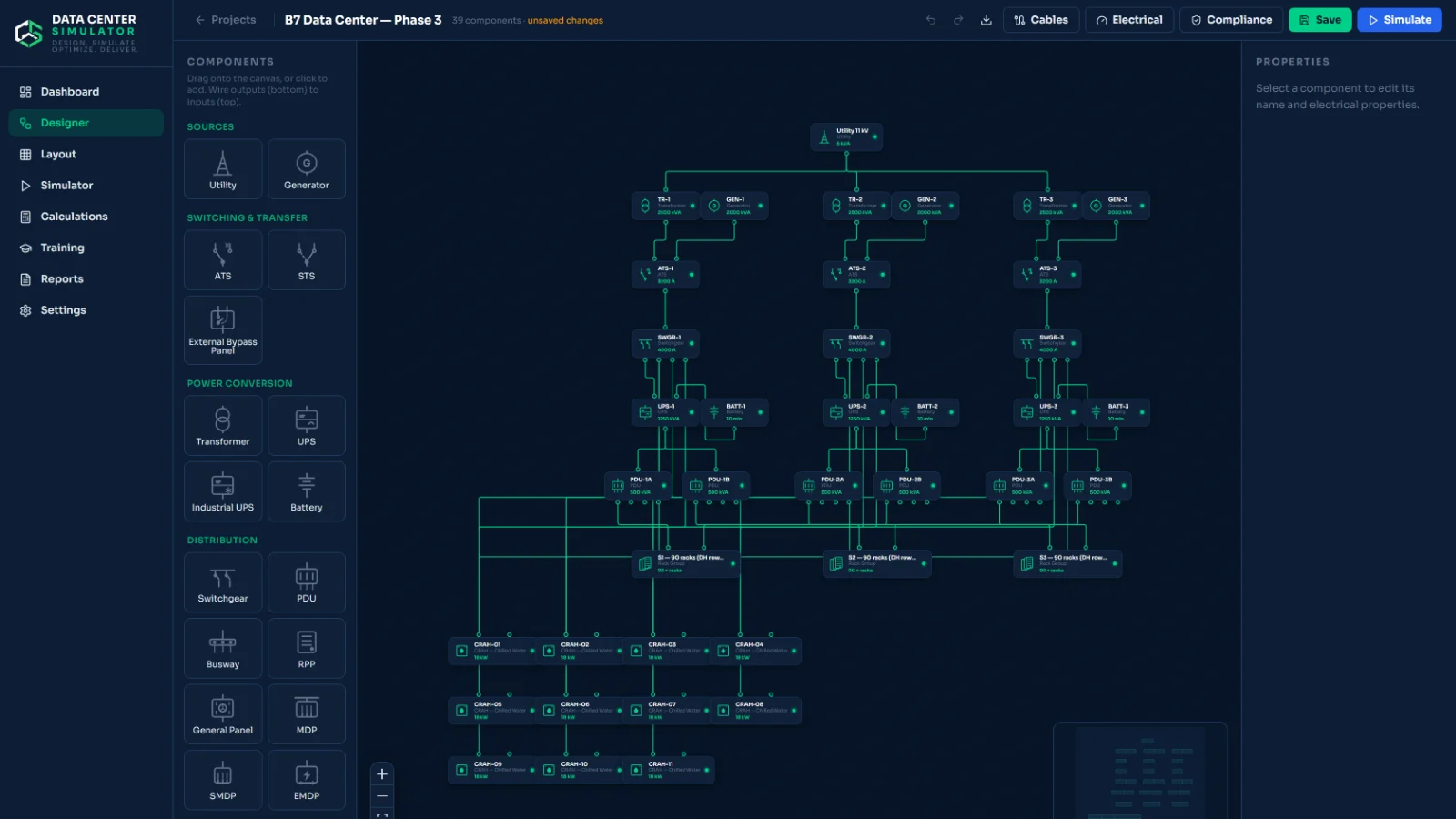
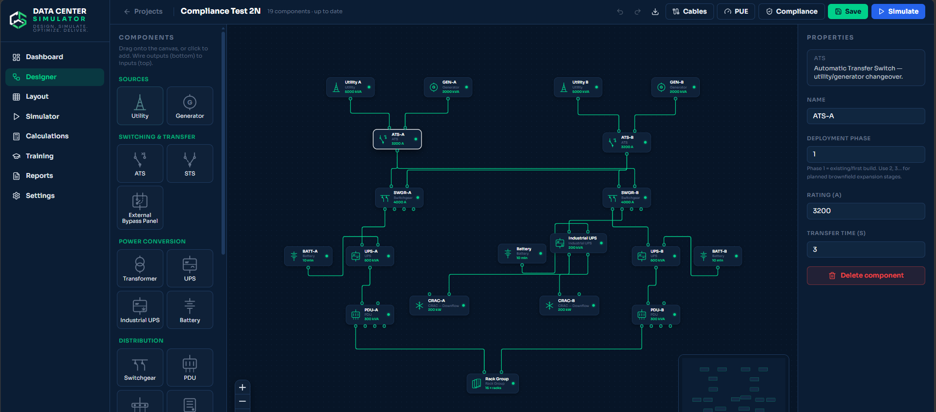
Designer · Single Line Diagram
Single line diagram of a 2N topology built in the designer, from utility and generator down through ATS, UPS and PDU to the rack groups
Single line designerDrag and connect utility, generators, transfer, UPS, batteries, PDUs and racks — the model behind every result on this page.
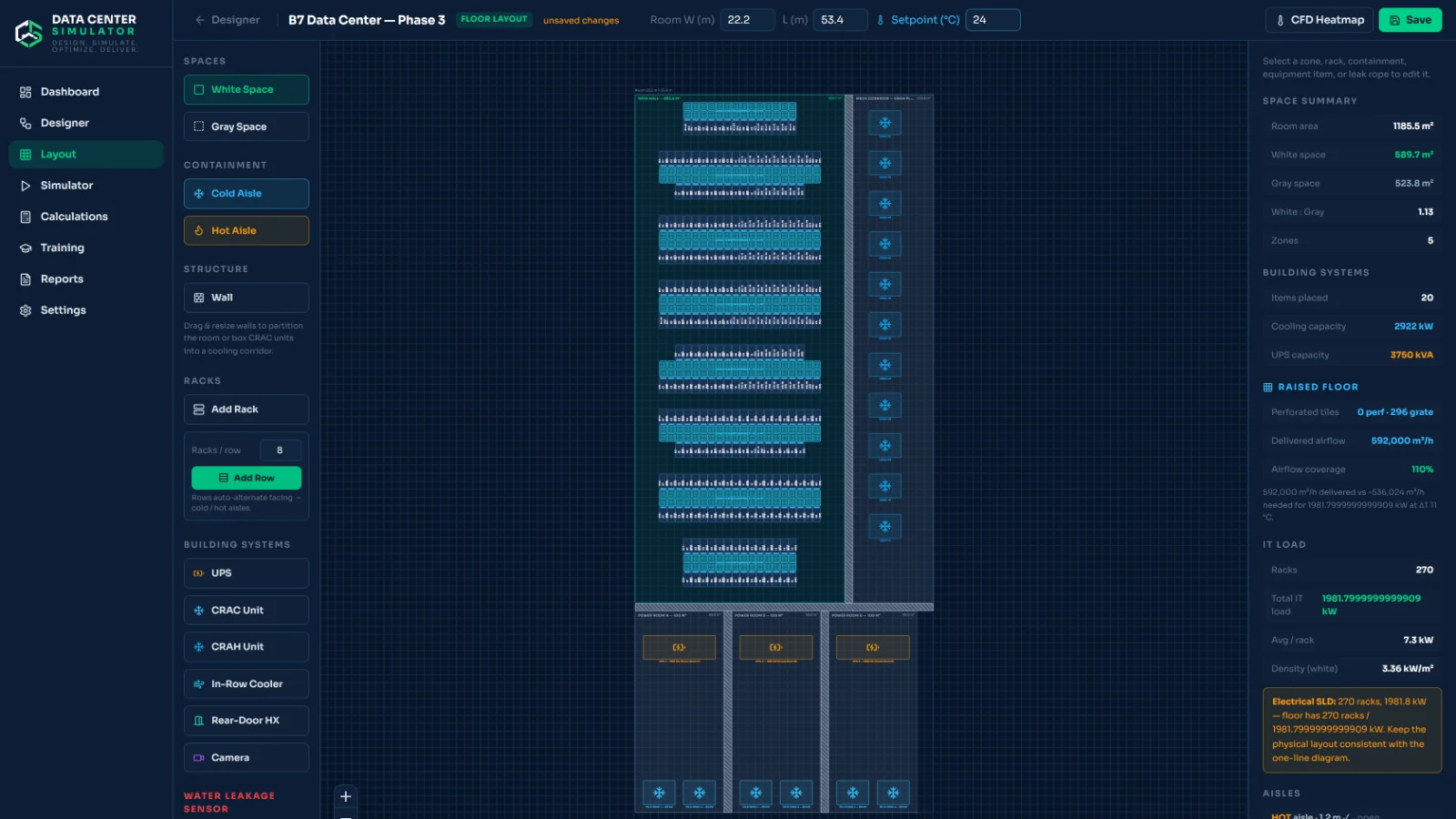
Layout · Floor Plan
White space floor plan with rack rows, aisles and equipment placed to scale
Floor layoutPlace rows, aisles, CRAC units and containment to scale, tied to the same components as the single line.
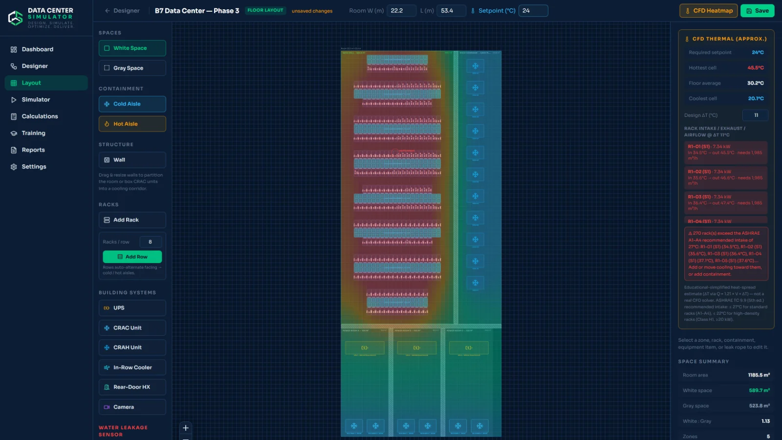
Layout · Thermal Map
Thermal map of the floor showing hot and cold aisle temperature distribution across the rack rows
Thermal mapSee where the heat actually goes before the racks are loaded, and which rows lose containment first.
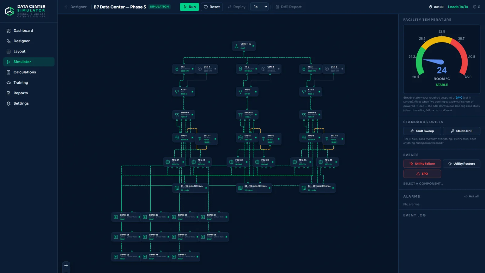
Simulator · Failure Drill
Simulator running a utility failure drill with the load transferred to generator and a live event timeline
Failure simulationInject utility loss, EPO and maintenance modes, then watch the transfer happen and time it.
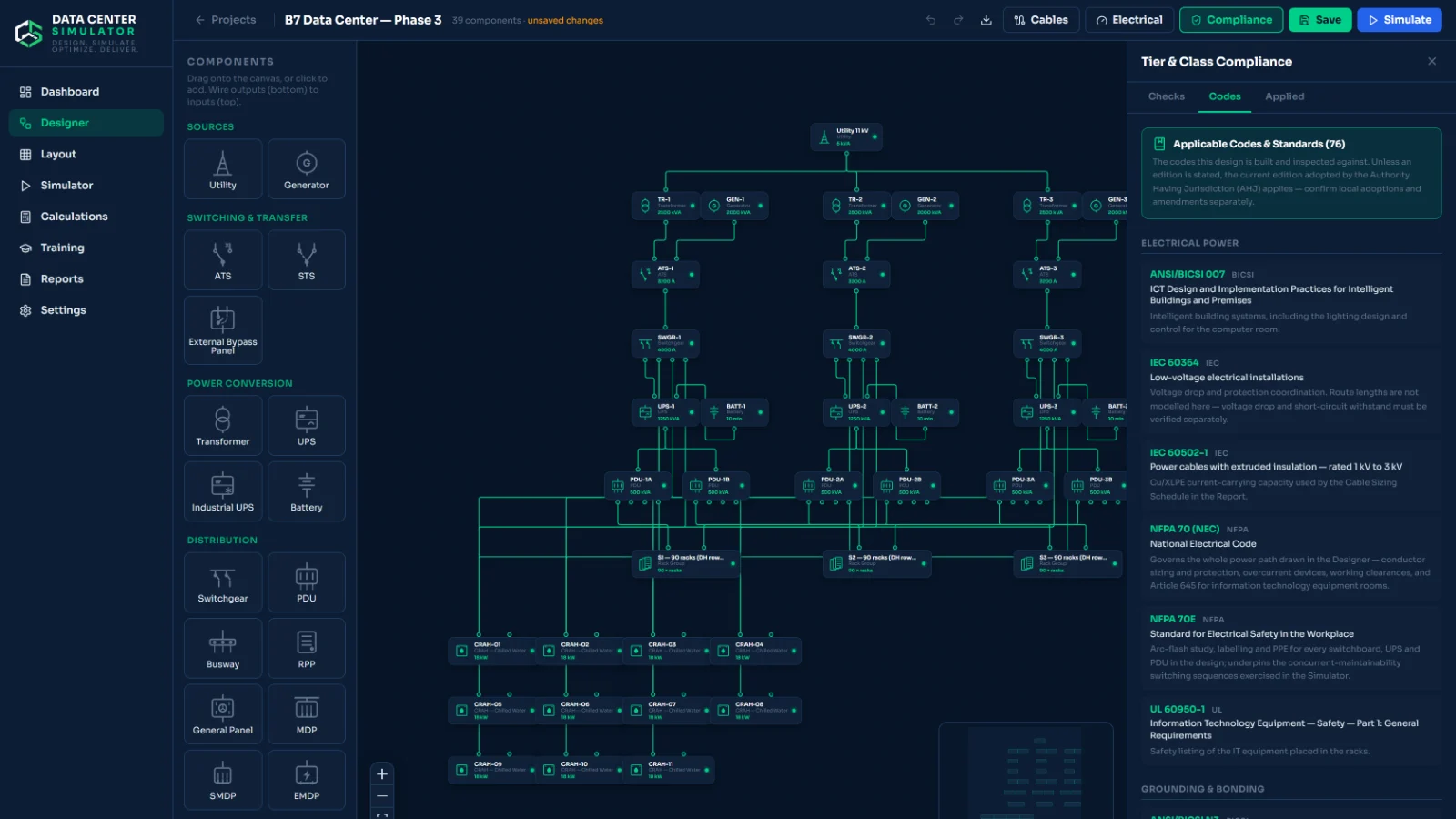
Compliance · Codes Register
Applicable codes and standards register listing the normative documents that apply to the design, organised by subject
Codes registerThe 76-document register behind the verdict — organised by subject, and printed into the report.
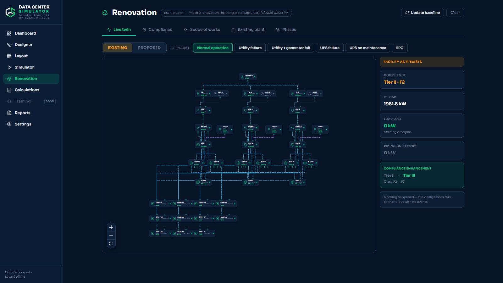
Renovation · Live Twin
The Renovation workspace running the same scenario against the existing facility and the proposal, showing the compliance change from Tier II Class F2 to Tier III Class F3
Existing versus proposedRun the same fault against the facility as captured and as you propose to leave it. The Tier and Class movement is the case for the works, stated as a result rather than a claim.
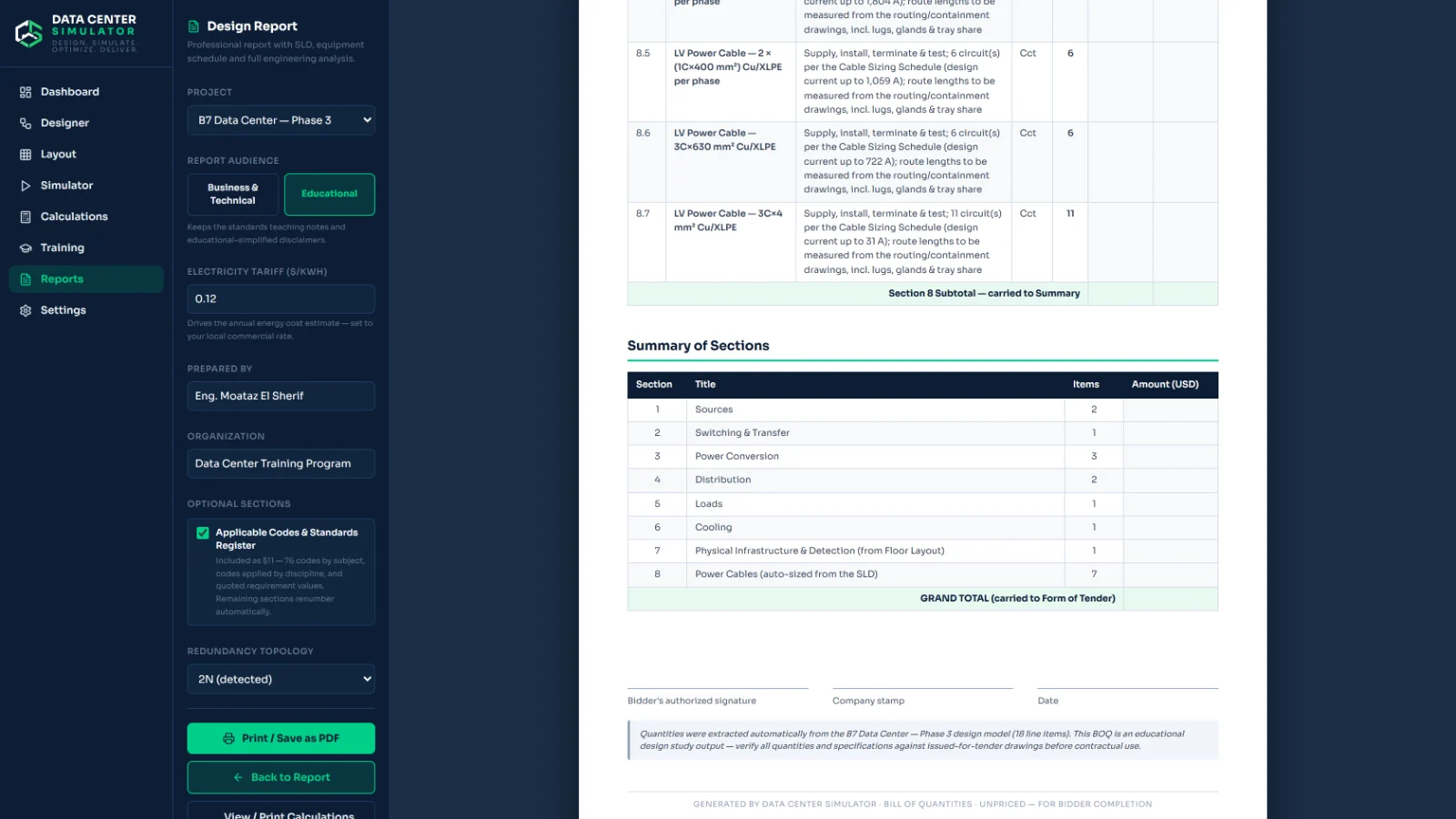
Reports · Bill of Quantities
Bill of quantities generated from the model, itemising equipment with quantities ready for pricing
Bill of quantitiesCounted from the model itself, not typed by hand — so it cannot disagree with the drawing.
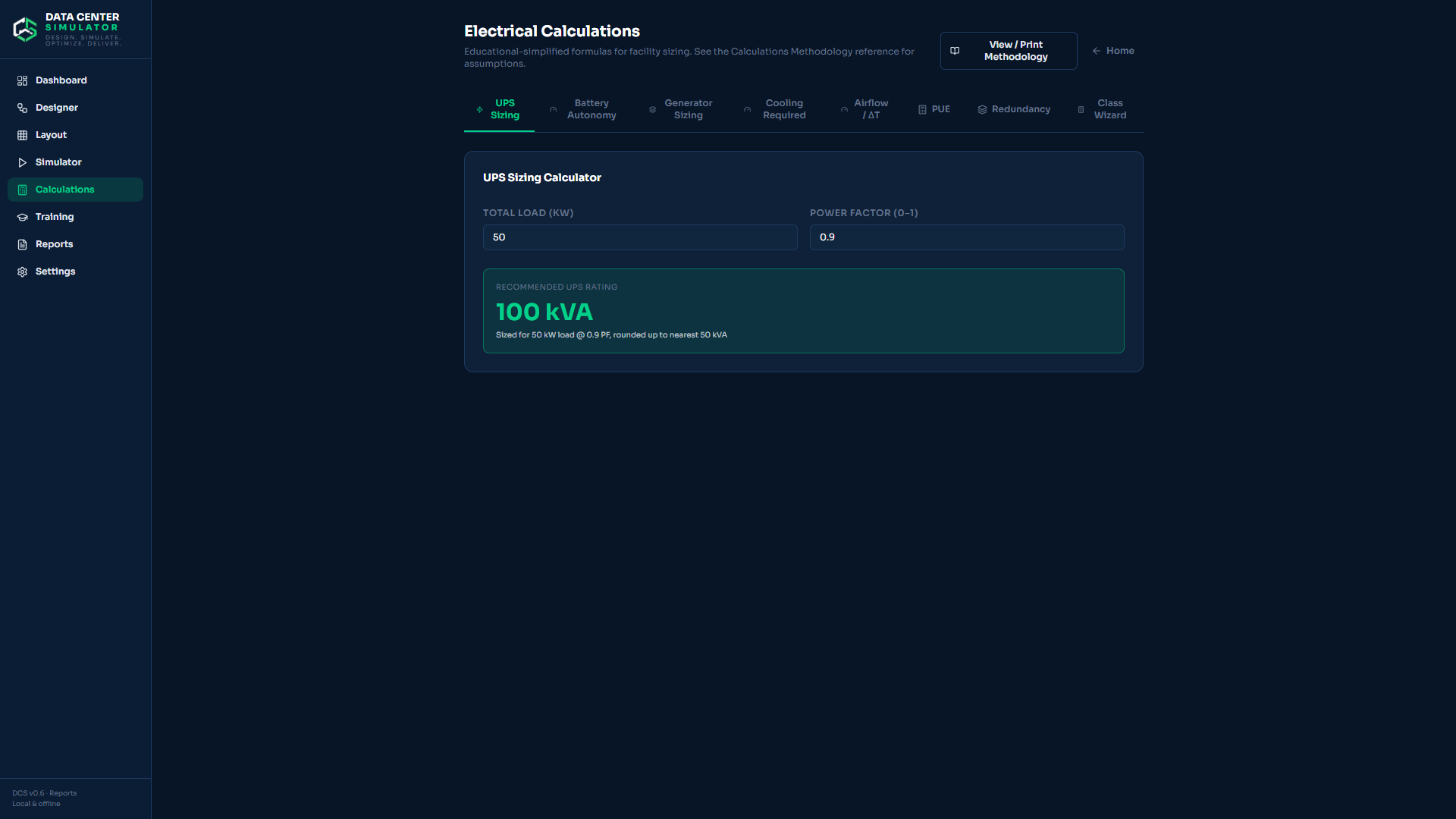
Calculations · UPS Sizing
Electrical calculations workspace showing the UPS sizing calculator recommending a 100 kVA rating
Electrical calculationsUPS sizing, battery autonomy, generator sizing, cooling, PUE and redundancy — with a printable methodology.
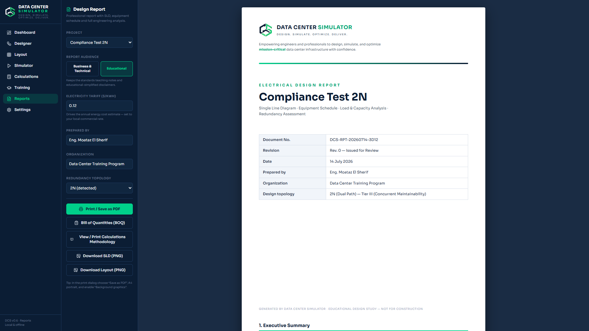
Reports · Design Report
Report generator producing a document-numbered electrical design report for a 2N Tier III topology
Report generatorDocument-numbered design reports, bills of quantities and SLD exports — ready for review.
REPORT INTELLIGENCE

Engineering outputs that speak to every stakeholder.

Convert simulation evidence into clear technical, operational and executive reporting — all generated from the same source model.

Engineering validation reportPDF · PNG · JSON
92/100
Power path verifiedCooling capacity verifiedDrill evidence attached
GET STARTED

Three steps.
No account, no internet.

Both downloads are a single Windows file. Nothing to install, no Node.js, no sign-up — double-click and the software opens in your browser, running entirely on your own machine.

01

Try the demo

The real application, restricted where the finished deliverable is. Design, simulate and get a genuine Tier / BICSI Class verdict on a facility you draw yourself.

Download the demo
Windows · 90 MBNo licence needed
02

Download the software

The complete edition. It comes to you with your licence key — one file, no installer. It opens on an activation screen that shows the Machine ID your key is issued against.

Sent with your licence
Windows · 90 MBDelivered on purchase
03

Request your licence

Open the software, copy the Machine ID it shows you, and send it over. You get a key back that works on that computer, offline, for as long as your licence runs.

Send my Machine ID
WhatsApp · fastestor email instead
Windows may warn you about an unknown publisher. Both files are unsigned while the code-signing certificate is being issued. Choose More info → Run anyway, or ask and the file will be sent to you directly.
LICENSING

Buy the licence. Run it on your own machine, offline.

Data Center Simulator is desktop software. It installs on your computer, keeps every project on your own disk, and never needs an internet connection to run.

01TRY IT FIRST

Demo

The complete application, restricted where it matters. Draw, simulate, and see the compliance verdict on your own design.

Free
No licence key needed · no account · no expiry
DOWNLOAD34 MB
Download the demo
  • Single line designer and floor layout
  • Failure simulation and thermal map
  • Tier / BICSI Class verdict
  • Report readable on screen, 4 sections
  • Printing, PDF export and file downloads
  • Renovation: existing vs. proposed
  • Codes register and Bill of Quantities
  • Engineering calculations
03TEAMS & INTEGRATORS

Company & Enterprise

Several computers, a perpetual term, or a licence shaped around how your practice actually works.

Custom
Multi-seat · perpetual available · invoiced
LICENCE2+ computers
Talk to us
  • Everything in Professional
  • Volume pricing per computer
  • Perpetual licence, no renewal date
  • Company invoice and purchase order
  • Direct support from the engineer who built it
  • Priority on feature requests
Every licence is tied to one computer and works completely offline. Changing computer? The replacement key is free. Ask about team and integrator pricing →
SIMULATION-FIRST ENGINEERING

Build with confidence.
Operate with evidence.

Download the demo, try it on a facility of your own, and ask for a licence when you are convinced. The engineer who built the software answers you directly.